


Trakonta ltd, 54031 Ukraine, Nikolaiv city, Electronnay street 81/4, E-mail: trakonta@gmail.com Tel: +380512714945; Mob, Viber: +380503180260

TECHNOLOGIES OF PULSE IMPACT ON MATERIAL
Technologies using high impulse currents belong, together with explosive currents (using explosives), to high-speed ones. In this case, an intense force effect on the object being processed is realized. At the same time, a high speed is imparted to the object, which opens up new technological possibilities. For example, the appearance of plastic properties in brittle materials (molybdenum alloys).
The technologies using strong impulse currents include electrohydraulic (high-current discharge in liquid), electroerosive and magnetic-pulse processing of materials (creating a strong pulsed magnetic field and organizing the force action of this field on the object being processed). Let's Consider the Electrophysical Basics of Technology.
The following technologies are presented on our website:
As a working medium in installations, as a rule, industrial water or other liquids are used. Usually, an electrohydraulic installation consists of an energy storage device (Figure 1), a charger device (CD) and a technological unit (TU) containing a certain volume of liquid, a system of electrodes between which a pulsed discharge is created, and a processed object located near the discharge channel (K).
The energy storage device, as a rule, is a bank of high-voltage pulsed capacitors with a capacity of C.
The energy storage device, as a rule, is a bank of high-voltage pulsed capacitors with a capacity of C.
Trakonta ltd
TECHNOLOGIES OF PULSE IMPACT ON MATERIAL
TECHNOLOGIES OF PULSE IMPACT ON MATERIAL

The capacitor bank is connected to the electrode system in the technological unit through an discharger (D), the presence of which allows the capacitor C to be charged to the required voltage from the charger of the charger with a relatively small current. The connection of the energy storage unit to the technological units is performed by a low-inductive cable, for which special high-voltage coaxial cables are used. The use of coaxial cables, in addition to reducing the inductance of the discharge circuit, weakens the electromagnetic fields near the operating installation.


Electrohydropulse technology
With a pulsed electric discharge in a liquid, energy is rapidly released in the discharge channel. As a result, the pressure in the discharge channel is much higher than the external one, the channel rapidly expands, which leads to the appearance of a shock wave and liquid flows.
The shock wave is a jump in the density of the medium propagating from the channel at a speed exceeding the sound one. The pressure at the front of a shock wave in a liquid can reach tens of kilobars. The impact of this pressure on the processed object can cause structural rearrangement of the object material (crushing of brittle materials, deformation, surface hardening, etc.). Fluid flows, propagating at a speed of 102 ч 103 m/s, transfer kinetic energy to the processed object, causing, like a shock wave, its mechanical changes. Mechanical manifestations of a pulsed discharge in a liquid are usually called the electrohydraulic effect, and installations using this effect are called electrohydraulic.
The shock wave is a jump in the density of the medium propagating from the channel at a speed exceeding the sound one. The pressure at the front of a shock wave in a liquid can reach tens of kilobars. The impact of this pressure on the processed object can cause structural rearrangement of the object material (crushing of brittle materials, deformation, surface hardening, etc.). Fluid flows, propagating at a speed of 102 ч 103 m/s, transfer kinetic energy to the processed object, causing, like a shock wave, its mechanical changes. Mechanical manifestations of a pulsed discharge in a liquid are usually called the electrohydraulic effect, and installations using this effect are called electrohydraulic.
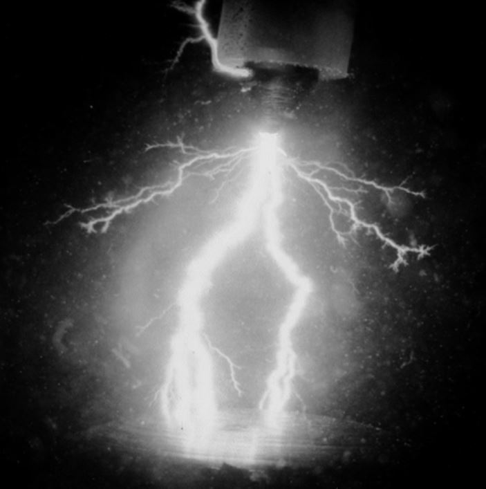
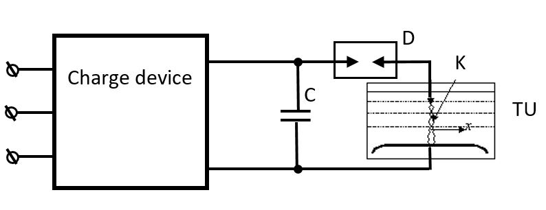
Figure 1. Schematic diagram of an
electro-hydraulic such installation
electro-hydraulic such installation
Discharger D can be controlled or uncontrolled. It is, as a rule, a two-electrode or three-electrode (trigatron) air spark gap, in some cases placed in a sound-insulating case. In installations with a high discharge repetition rate, compressed air is blown through the gap of the spark gap, and the electrodes are cooled with water. The presence of a technological block is typical for installations designed for processing transportable parts or materials (for example, parts in mechanical engineering and metalworking, raw materials in the mining and construction materials industry, etc.) In such electro-hydraulic installations as drilling installations, destruction of oversized pieces rocks, for echolocation of reservoirs, the technological unit is absent and instead a movable electrode system is used, immersed in a well filled with liquid, or in a reservoir. The principle of operation of a typical hydraulic installation is explained by the graphs of changes in time of the main electrical parameters shown in Figure 2.
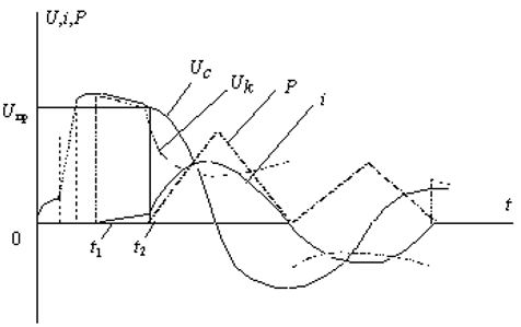
Figure 2. Voltage change on the capacitor Uc, on the discharge channel Uk, discharge current i and power P in time t.
Until the moment t1, the storage device is charged: the voltage across the capacitor C grows to U1 = 103 ÷ 105 V. At the moment t1, the storage device is connected to the spark gap in the liquid and the process of electrical breakdown of the gap begins. Upon completion of the breakdown at time t2, the channel stage of the discharge begins. The voltage uс during the time t2 - t1 drops somewhat (to Upr) due to the drainage of the charge from the capacitor C due to the electrical conductivity of the medium in the gap. If during breakdown the current i flowing through the gap increases insignificantly, then upon completion of the breakdown it increases sharply. Typically, the current during the channel stage has a shape close to sinusoidal with high attenuation.
The shape of the voltage across the gap uk reflects the nonlinearity of the resistance of the discharge channel. The power pulse P developed in the channel has a shape close to triangular.
In those cases when the energy losses during the breakdown time t2 - t1 in the gap are unacceptably large or, at the operating voltage, a stable breakdown of the gap is not ensured at the required distance between the electrodes, before each discharge, the electrodes are short-circuited with a thin wire, which explodes under the action of the current.
During a discharge or an electric explosion of a wire in a liquid, a shock pressure wave and a gas cavity pulsating in size arise, the change in position of which relative to the channel axis in time is shown in Fig. 3, and, accordingly, curves 1 and 2.
The discharge channel at the beginning of the process expands at a maximum rate. After the cessation of the current flow, the cavity of the discharge channel continues to expand due to the inertia of the environment, reaches its limiting dimensions, and then begins to contract. With the expansion of the cavity, the temperature and pressure in it fall, and with compression, they increase, which leads to damped pulsations of the cavity. Usually, the oscillation period of the cavity is several orders of magnitude longer than the discharge duration. The maximum dimensions of the cavity, depending on the energy released during the discharge and on the conditions of the flow of hydrodynamic processes in the technological block, range from several centimeters to tens of centimeters.
In the case of using an exploding wire, the picture of mechanical manifestations changes somewhat (Figure 3, b). From the moment the storage t1 is connected, the wire starts to warm up and its diameter grows relatively slowly. By the time the electric explosion starts t3, weak shock waves are separated from individual sections of the wire, propagating at a speed close to the speed of sound. At the moment of completion of the explosion t4, a powerful shock wave appears, overtaking the previously arising ones, and then the process proceeds in the same way as in the discharge due to the gap breakdown.
Due to energy losses in the connecting wires and storage elements, in the discharge channel and in the gas cavity, only a small part of the accumulated energy is supplied during the breakdown of the gap or explosion of the wire to the object of processing. However, during a discharge in a liquid, high energy concentrations and processing rates are achieved, which determines the fields of application of electrohydraulic installations. These are, first of all, high-speed deformation of metals, destruction and crushing of brittle materials, cleaning of metal parts from molding sands, scale, echolocation of water bodies, etc.
Due to energy losses in the connecting wires and storage elements, in the discharge channel and in the gas cavity, only a small part of the accumulated energy is supplied during the breakdown of the gap or explosion of the wire to the object of processing. However, during a discharge in a liquid, high energy concentrations and processing rates are achieved, which determines the fields of application of electrohydraulic installations. These are, first of all, high-speed deformation of metals, destruction and crushing of brittle materials, cleaning of metal parts from molding sands, scale, echolocation of water bodies, etc.
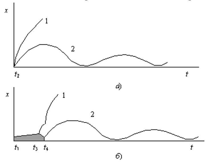
Figure 3. Change in the position of the shock wave (curves 1) and the boundaries of the gas cavity (curves 2) with a discharge in a liquid caused by breakdown (a) and explosion of a conductor (b)
Electrical discharge machining of materials
Electric discharge machining is understood as the processing of metals using electrical erosion that occurs when a pulse discharge is organized between the workpiece and a special electrode-tool. Electrical discharge machining is carried out in order to give a part of the required shape (dimensional processing), harden the surface or apply a protective coating on it.
A schematic diagram of the processing of a part on an electric discharge machine is shown in Figure 4. During processing, the machine itself 1 with a working bath 2 is used, in which there is a table 3 for installing an electrode-product 4 with movement in two coordinates; 5 - regulator of the electrode-tool feed; 6 - power source - pulse generator; 7 - a system for supplying a working fluid, consisting of pumps, filters, a tank, etc .; 8 - electrode tool.
A schematic diagram of the processing of a part on an electric discharge machine is shown in Figure 4. During processing, the machine itself 1 with a working bath 2 is used, in which there is a table 3 for installing an electrode-product 4 with movement in two coordinates; 5 - regulator of the electrode-tool feed; 6 - power source - pulse generator; 7 - a system for supplying a working fluid, consisting of pumps, filters, a tank, etc .; 8 - electrode tool.
The power supply 6 converts an alternating current of industrial frequency into a pulsed current with an adjustable pulse repetition rate from hundreds to hundreds of thousands of hertz, an amplitude from fractions to thousands of amperes, a duty cycle from 1.01 to 5 ÷ 10, a pulse duration from fractions to several thousand microseconds. By changing these parameters, the technological mode of processing is established.
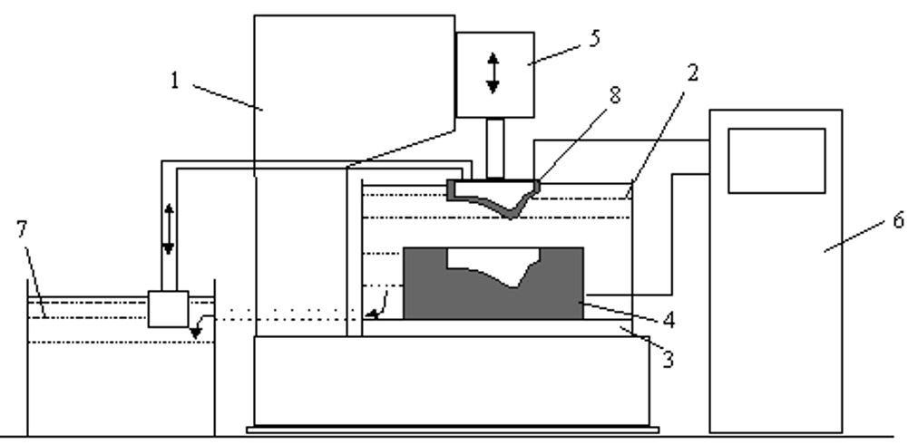
Figure 4. Electric discharge machine with auxiliary devices for power supply and supply of working fluid
The supply regulator 5 automatically changes the position of one of the electrodes in order to maintain a given interelectrode gap, which changes due to the erosion of the electrode material.
The supply system 7 serves to regulate the flow rate and purify the working fluid supplied in order to facilitate the removal of process products and cooling directly into the interelectrode gap (working area) and into the bath 2 of the machine.
There are two types of electrical discharge machining: electrospark and electric pulse.
Electrospark processing is performed with short current pulses (less than 100 μs). Conventionally, such discharges are called spark discharges, from which the name of the treatment follows.
Electrical pulse processing is characterized by longer current pulses (more than 100 μs), at which the discharge in its characteristics approaches the arc: with characteristic zones and a channel column, which is characterized by small voltage gradients.
The principle of implementation of electrical discharge machining is based on the thermal effect of the discharge channel on the workpiece. In the discharge channel, including the near-electrode zone, energy is released in a short time, heating the gas medium of the channel (mainly metal vapor) to a temperature of several thousand degrees. Due to thermal conductivity, a heat flux is formed from the discharge zone, which quickly heats up a metal workpiece immediately adjacent to the discharge site, melts and partially evaporates a certain amount of metal, forming an erosion hole. To organize the discharge with the required parameters and to evacuate the erosion products (vapor and molten metal particles), the discharge is performed in a process fluid (kerosene, oil, water). Figure 5 shows the open (a) and closed (b) working areas of the EDM machine.
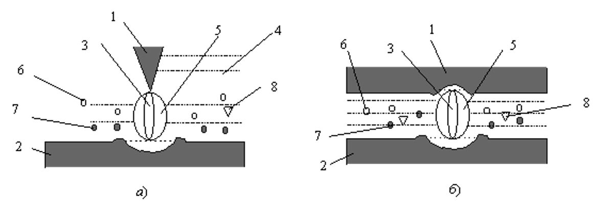
Figure 5. Schematic of an open (a) and closed (b) working area with a single discharge:
1 - anode; 2 - cathode; 3 - discharge channel; 4 - working environment; 5 - gas bubble;
6 - bubbles of steam or gas; 7 - solid particles; 8 - pyrolysis products
1 - anode; 2 - cathode; 3 - discharge channel; 4 - working environment; 5 - gas bubble;
6 - bubbles of steam or gas; 7 - solid particles; 8 - pyrolysis products
The voltage of the power source of electrical discharge installations is usually several tens of volts (in some cases, hundreds of volts), so the distance between the workpiece 2 and the electrode-tool 1 is microns. The tool electrode is movable. Discharges occur in places where the distance between the electrode and the workpiece is minimal. The formed hole leads to an increase in the distance, and the discharge at the next pulse occurs in a different place. Thus, the entire surface between the electrode and the part is gradually processed, the electrode 1 is slowly introduced into the hole formed in the part 2. Erosion products 7 (small solidified particles of material, both the part and the electrode), pyrolysis products 8 are carried out by liquid 4 from the hole.
The main advantages of electrical discharge machining are the ability to process metals with any strength, including high-strength alloys, as well as the ability to make holes, cut lines of complex configuration. For example, using an electrode in the form of a spiral, it is possible to make a hole following the shape of the electrode in a workpiece of any strength. It is impossible to perform a similar operation with any other technological methods.
An important feature of EDM is the ease of regulating the energy released in the discharge by changing the capacity of the power source. This provides the desired mode: coarse (rough) or softer, with a smoother surface of the workpiece (finishing modes).
Nowadays, EDM technology is widespread. Modern production of many devices, tools, products from hard alloys, dies, dies, punches and much more is impossible without electrical discharge machines.
Magnetic pulse processing of materials
Magnetic-pulse processing of materials is based on the use of electrodynamic forces, which in pulse modes can reach very high values. If the pressures created by electrodynamic forces exceed the ultimate strength, then the workpiece is deformed. This process is often referred to as magnetic stamping.
During magnetic-pulse processing, the electrical energy stored in the capacitor bank is converted, during discharge to the inductor or directly to the workpiece, into the energy of a pulsed magnetic field, which performs the work of deformation of the electrically conductive workpiece.
Pulse current generators for magnetic pulse processing
Low-inductance capacitive energy storage devices are used in pulse current generators for magnetic-pulse installations. The charging voltage of storage devices is usually 5–20 kV.
The drives are equipped with pulse capacitors. In installations with a large accumulated energy, capacitors are combined into blocks with their own discharge current switches. The block principle of the storage device allows achieving low values of inductance and active resistance of the discharge circuit and avoiding the danger of explosion of capacitors in case of damage during charging. The internal inductance of the discharge circuit of the installation can be reduced to 10-8 H.
The installations use pulse capacitors with paper-oil insulation impregnated with capacitor or castor oil. With a small number of parallel-connected capacitors, capacitors with a low internal inductance are chosen to achieve a high frequency of the discharge current.
The capacitors in the installation or within the unit are connected in parallel by a low-inductance busbar. Two types of busbars are used: cable and flat, carried out by wide buses applied directly to the capacitor leads.
Air or vacuum dischargers and ignitrons are used as switches for the discharge current. In the simplest installations, mechanical switches are used - two-electrode arresters that are triggered when the electrodes come together. If it is required to precisely synchronize the discharge with the operation of the rest, for example, measuring equipment, or to ensure the simultaneous operation of separate arresters, use controlled arresters - trigatrons or ignitrons.
The drive is charged from a high DC voltage source, which includes a step-up transformer, rectifier, and other components. A necessary element of the installation is a grounding device that discharges the capacitors through a low-resistance resistor and short-circuits the capacitor leads after the end of work. The charger and energy storage device are usually housed in a metal grounded housing, the doors of which are fitted with a lock.
The discharge circuit is connected to the grounded body of the installation at one point - usually at the point where the inductor is connected.
All rights reserved by Trakonta 1996 – 2021