Trakonta ltd


Trakonta ltd, 54031 Ukraine, Nikolaiv city, Electronnay street 81/4, E-mail: trakonta@gmail.com Tel: +380512714945; Mob, Viber: +380503180260

Products
The products manufactured by our company are intended for the implementation of high-voltage pulse technologies, as well as for other technologies where high voltage is applied.
Pulse current generators
The technical tool for the implementation of these methods of converting electrical energy is a high-voltage powerful pulse generator (PCG). The PCG is a source of high-voltage current pulses and is designed to increase the mains voltage with its subsequent rectification and charging of high-voltage pulse capacitors, commutation of energy stored in the electric field of capacitors.
Trakonta ltd
Products
Products
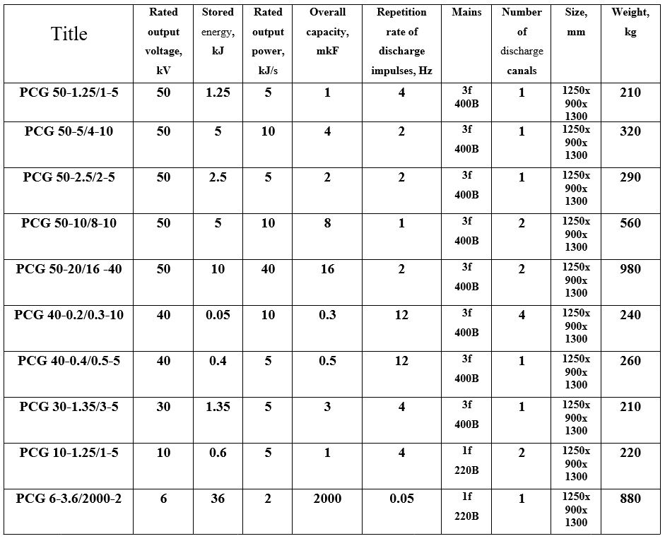
Electrical specifications of PCGs.
Rated Output Voltage
The output voltage is continuously adjustable by spark gap
from 0 to 100 % (full scale). PSGs have built up electronic module, which allow to realize fine adjustment of output voltage impulse in the range from 0 to 70 kV.
Output current
The output current depend on load parameters. Digit current pulse amplitude can be up to 1 MА.
Repetition rate of discharge impulses
Repetition rate of discharge impulses regulation: ± 0.05 % of full current (for 0 – 100 % load).
Stored energy
The stored energy can be discretely regulated by adding capacitors in parallel or series.
Protections:
Against short circuit & HV arc to ground.
Shutdown on over temperature & open interlock.
Operating temperature: from 0 to 40°C.
Mains Voltage: 380-400 VAC ±10% 45 – 65 Hz 3 Phases + Earth.
Inrush current: limited to full power operating current.
Discharger is cooling by air. Reversibility and floating outputs. (Polarity can be positive, negative, floating or reversible). The PCG can have a modular structure, and consist of separate independent cells and a united control unit, assembled in a post.
Customer remote adaptation.
Any special requests can be considered.
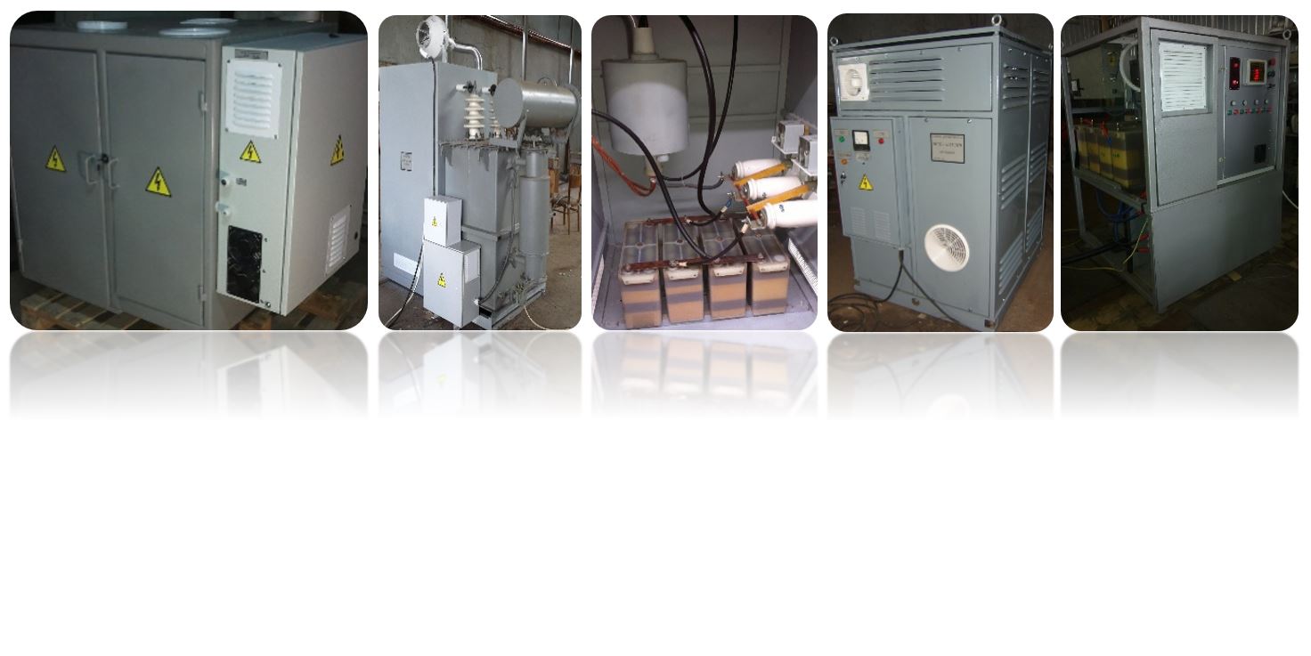
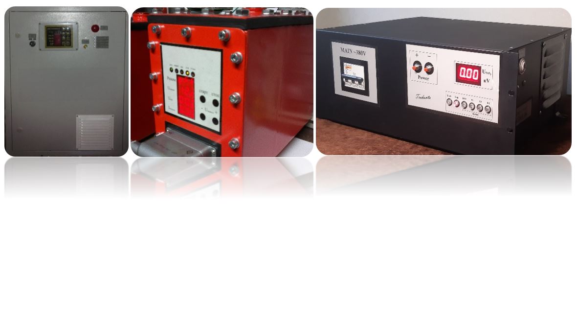
High Voltage Charge Devices
High voltage Charge Devices (HVCDs) are the most important component of pulse current generators and other devices. HVCDs are designed for charging capacitive energy storage. Our HVCDs have minimum weight and dimensions. HVCDs are equipped with systems for regulating the charging current over a wide range. The HVCD can operate on any load from idle to short circuit and have remote control capabilities. The polarity of the output voltage relative to the zero terminal can be any.
Rated Output Voltage
The output voltage is continuously adjustable by spark gap
from 0 to 100 % (full scale). PSGs have built up electronic module, which allow to realize fine adjustment of output voltage impulse in the range from 0 to 70 kV.
Output current
The output current depend on load parameters. Digit current pulse amplitude can be up to 1 MА.
Repetition rate of discharge impulses
Repetition rate of discharge impulses regulation: ± 0.05 % of full current (for 0 – 100 % load).
Stored energy
The stored energy can be discretely regulated by adding capacitors in parallel or series.
Protections:
Against short circuit & HV arc to ground.
Shutdown on over temperature & open interlock.
Operating temperature: from 0 to 40°C.
Mains Voltage: 380-400 VAC ±10% 45 – 65 Hz 3 Phases + Earth.
Inrush current: limited to full power operating current.
Discharger is cooling by air. Reversibility and floating outputs. (Polarity can be positive, negative, floating or reversible). The PCG can have a modular structure, and consist of separate independent cells and a united control unit, assembled in a post.
Customer remote adaptation.
Any special requests can be considered.
High Voltage Charge Devices
High voltage Charge Devices (HVCDs) are the most important component of pulse current generators and other devices. HVCDs are designed for charging capacitive energy storage. Our HVCDs have minimum weight and dimensions. HVCDs are equipped with systems for regulating the charging current over a wide range. The HVCD can operate on any load from idle to short circuit and have remote control capabilities. The polarity of the output voltage relative to the zero terminal can be any.


Trakonta ltd Trakonta ltd
Physical description of PCGs
Trakonta ltd Trakonta ltd
Physical description of High Voltage Charge Devices
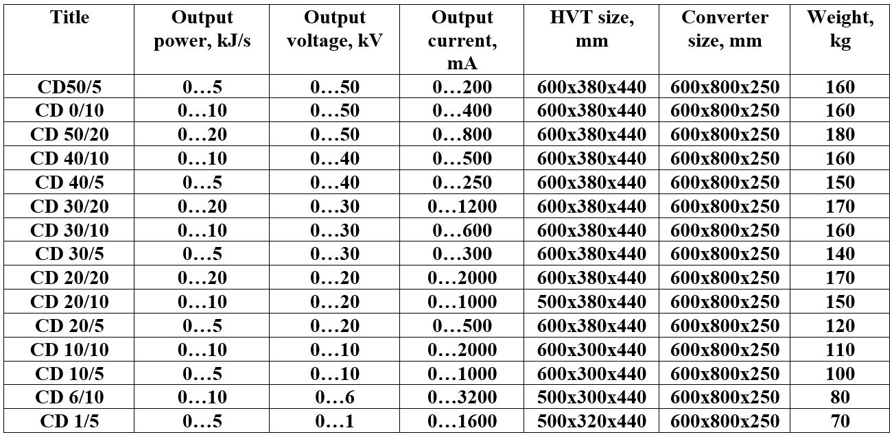
Electrical specifications of High Voltage Charge Devices
Output Voltage and Output Current
Both Voltage Output and Current Output are continuously adjustable.
from 0 to 100 % (full scale).
In remote mode: by using power buttons resolution 0.05%.
Current regulation
Load Regulation: ± 0.05 % of full current (for 0 – 100 % load).
Protections:
Against short circuit & HV arc to ground.
Shutdown on over temperature & open interlock.
Operating temperature: from 0 to 40°C.
Efficiency: > 87 % full load.
Mains Voltage: 380-400 VAC ±10% 45 – 65 Hz 3 Phases + Earth.
Inrush current: limited to full power operating current.
Air Cooling by air. Reversibility and floating outputs. (Polarity can be positive, negative, floating or reversible). The source can have a modular structure, and consist of separate independent cells and a united control unit, assembled in a post. Control mode secures cells work control, their uniform load.
Customer remote adaptation.
We can offer you high-voltage charge devices, the parameters of which are in the following ranges:
1. Output voltage Range: 0 ... 125 kV.
2. Output current range 0...100 A.
3. Output power range 0...60 kJ/s.
Any special requests can be considered.
High voltage dispersants for metal powders
Practice shows that as higher the pulse voltage applied to the electrodes, as smaller the particle size of the substance can be obtained. To obtain nanoparticles, it is advisable to use a pulse voltage of 10-30 kV. Installations have been developed that operate with high impulse voltages (up to 50 kV) and installations with pulse voltages up to 1000 V. Impulse energy and pulse repetition rate are regulated within wide limits.
Powerful universal high-voltage dispersant for nanopowder production VDM 25-4.8/10
Trakonta ltd
Physical description of the device:
Output voltage: adjustable 8 ... 25 kV.
output power: up to 10 kW (adjustable from 0.4 to 10 kW).
The energy of the capacitor bank: 1.5 kJ.
Output pulse repetition rate up to (at a maximum voltage of 25 kV):
6 Hz - energy 1.5 kJ.
Output pulse repetition rate up to (at a voltage of 15 kV):
16 Hz - energy 0.5 kJ.
Output pulse repetition rate up to (at a voltage of 10 kV):
30 Hz - energy 0.25 kJ.
Number of channels: 1.
Number of capacitors: 1 (5 μF x 25 kV).
Input voltage: 3-ph 400V.
Number of arresters: 1 (adjustable air).
Installation dimensions: 1000х1200х1700mm (height 1700).
Installation weight: 340 kg.
Universal high voltage disperser VD1-0.25/2
Trakonta ltd
Physical description of the device:
Output voltage: adjustable 400 ... 1000 V.
Output power: up to 2 kW (adjustable from 0.5 to 2 kW).
Energy of the capacitor bank: 25 J.
Output pulse repetition rate up to (at a maximum voltage of 1000 V):
80 Hz - energy 25 J.
Output pulse repetition rate up to (at voltage 800 V):
100 Hz - energy 16 J.
Output pulse repetition rate up to (at 600 V):
200 Hz - energy 9 J.
Number of channels: 1.
Number of capacitors: 1 (50 μF x 2000V).
Input voltage: 220V.
Number of arresters: 1 (thyristor).
Unit dimensions: 800x600x200mm (height 800).
Installation weight: 43 kg.
High-voltage dischargers (arresters)
A high-voltage discharger is a device designed to switch electrical energy due to electrical breakdown of an insulating medium. This is a device that instantly changes its electrical conductivity when a discharge occurs between the electrodes.
High-voltage dischargers are used as high-speed switches (usually of high energies) in pulse current generators, communication devices, location devices, and other devices.
Trakonta ltd Trakonta ltd
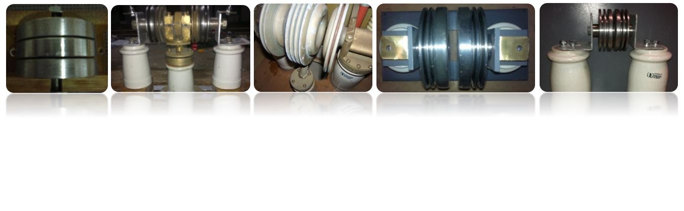
Physical description of air-spark dischargers
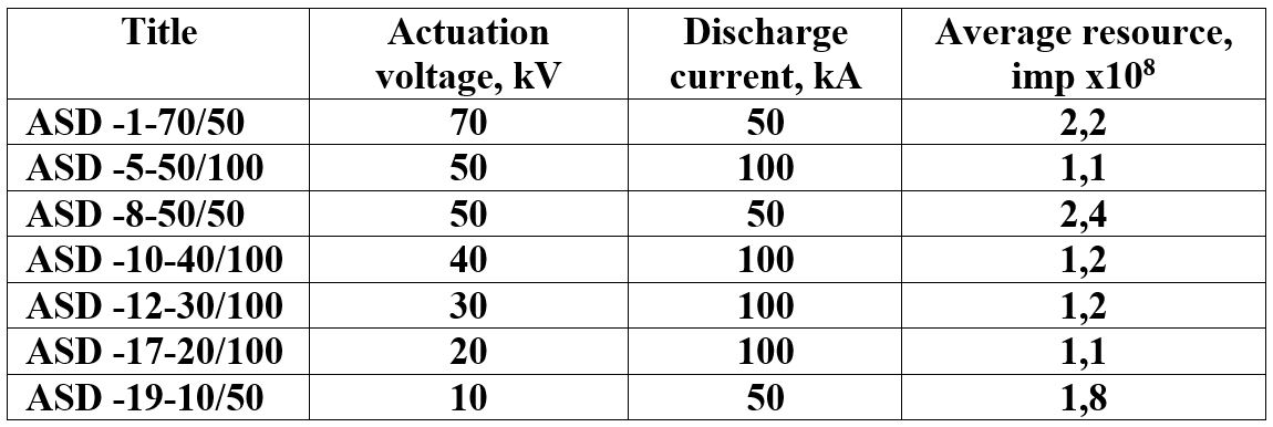
ASD (air-spark discharger), can be produced as controlled (with a middle electrode) and not controlled.
We can also offer air spark dischargers with the following parameters:
1. Range of switched voltages 0 ... 125 kV.
2. Range of response time 50… 300 ns.
3. Range of self-inductance 30 ... 300 nH.
4. Range of pulse repetition rate 0… 1000 Hz.
5. Energy range per pulse 0 ... 100 kJ.
6. Range of discharge current 1 ... 1000 kA.
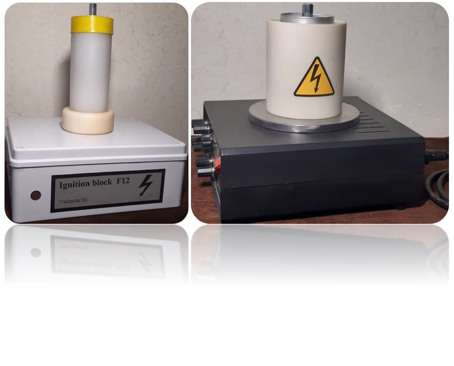
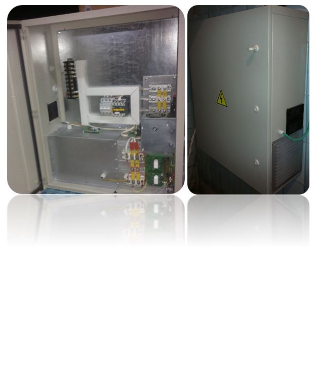
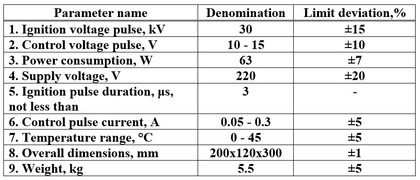
Control device for triggered discharger
The discharger control device or the spark gap ignition unit is designed to initiate the breakdown of the interelectrode gap at a given time. The high-voltage pulse generated by the ignition unit is fed directly to the switching electrodes of the spark gap from the high-voltage terminals. Structurally, the ignition unit is a housing in which a pulse high-voltage transformer and an electronic control unit are located. It has a socket for connecting to a network and a socket for connecting a control pulse.
To start the device, a positive control pulse is required - a voltage of 10-15 V, I = 0.05-0.3 A and a duration of at least 3 μs. The secondary winding of the transformer is isolated from the primary winding. The dielectric strength between the windings is up to 60 kV DC voltage.
We can also offer air spark dischargers with the following parameters:
1. Range of switched voltages 0 ... 125 kV.
2. Range of response time 50… 300 ns.
3. Range of self-inductance 30 ... 300 nH.
4. Range of pulse repetition rate 0… 1000 Hz.
5. Energy range per pulse 0 ... 100 kJ.
6. Range of discharge current 1 ... 1000 kA.
Control device for triggered discharger
The discharger control device or the spark gap ignition unit is designed to initiate the breakdown of the interelectrode gap at a given time. The high-voltage pulse generated by the ignition unit is fed directly to the switching electrodes of the spark gap from the high-voltage terminals. Structurally, the ignition unit is a housing in which a pulse high-voltage transformer and an electronic control unit are located. It has a socket for connecting to a network and a socket for connecting a control pulse.
To start the device, a positive control pulse is required - a voltage of 10-15 V, I = 0.05-0.3 A and a duration of at least 3 μs. The secondary winding of the transformer is isolated from the primary winding. The dielectric strength between the windings is up to 60 kV DC voltage.
Physical description of control device
The discharger control device is a converter of the control signal into a high-voltage pulse required to ignite the controlled discharger.
All rights reserved by Trakonta 1996 – 2021